(Part 4 of 13 in series, Scaf 101)
Remember when I said I’d start by explaining everything? Well, you should understand how the clamps work, so that you understand how to put them together. If you do it wrong, they wiggle loose and come apart surprisingly quickly.
Pro-tip: Scaf should be quiet! If you hear a rattle or tapping sound stop. Something is very loose — you probably forgot to tighten something. Or, you didn’t have things lined up correctly, then after the scaf is jostled a bit, things shift and voila! Loosey goosey. Learn to pay attention to your “scaf sense”. When your scaf sense tingles, stop and figure out what’s going on.
“omg Craig shut up already and let’s build something…” This is the last background information post. We’ll start building stuff in the next post. Please read this one carefully, this gets technical. But, if you understand this material, you’ll be a happy clamper later on.
Depth
On some of the clamps, you can actually insert the pipes too far. Usually, it’s the first pipe that you insert too far. In these pictures, the first shows the pipe inserted so far that the end of the pipe has bumped into the curved body of the clamp. That’s too far! You can see how the straight line of the side of the pipe looks out of whack. Tightening the screw will not fix this; although it will get tight. You will have two problems: 1) The overly inserted pipe might be in the way of some other pipe’s space, messing up alignment/lengths. 2) Things don’t turn out square/correct because when you start tightening everything else, this clamp is fighting the additional angle added by the mis-aligned pipe. If you get it right, your pipes make nice 90° (or 45° or whatever) angles.
WRONG:
RIGHT:
Bear in mind that the problem comes up when you cannot really see the angle you’re making. You have to sort of feel that the pipe is inserted correctly, while holding a pipe up over your head, or holding three pipes at once and aligning the clamp. You’ll get the hang of it.
But wait, it’s worse. Next you have to be thinking about whether each pipe will interfere with the other pipes. So in the “RIGHT” photo above, the pipe is still inserted too far. Why? Well the pipe inserted from the bottom of the photo looks like it has enough room. But the pipe inserted from your point of view probably should go father into the body. Or maybe it shouldn’t; maybe all three pipes need to be equally inserted for this setup. My point being that you have to pay attention. First, pay attention to my assembly hints. Later, you’ll understand intuitively how “an extra pipe width here”, or “a half pipe width there”, adds up to make your assemblies fit, or not fit. If I have included a close-up photo that shows the ends of pipes inside a clamp, then I’m thinking the insertion depth is really important in that clamp. As we go farther along with these setups, I’ve assembled (and photographed) some mistakes on purpose, and I’ll show you how it ends up messing up the setup and how to correct it.
Lands
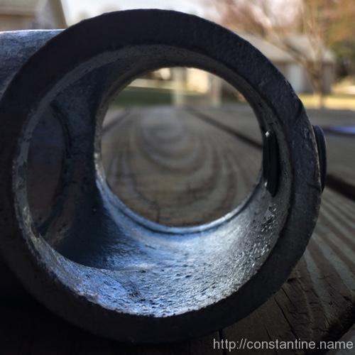
In machining, a “land” is the accurately machined part (of something) that some other thing is supposed to rest on. Pipe clamps are not machined (they are cast in molds) but they do have lands; the places where the clamp actually touches the pipe. In Kee Klamps, the lands are circumferential raised ridges on the interior of the clamp. Each set key presses on the pipe midway between the two lands; it’s like how you might press down on the middle of a board resting on two saw horses as you cut the end off. The set key is pressing in the middle, and instead of flat saw horses, the clamp has round ridges that cradle the other side of the pipe. Here are photos of some pipe lands:
Above: One land deep inside the clamp is easy to see. The other land is at the very face (closest to you in this view) of the clamp. (The already-inserted pipe is surely in far enough to be over both of its lands; in fact, it might be in so far as to hit the clamp body and cause that alignment problem discussed above.) When inserting a pipe in this view, the set screw will drive the pipe upward until it touches both lands, at the top of the photo.
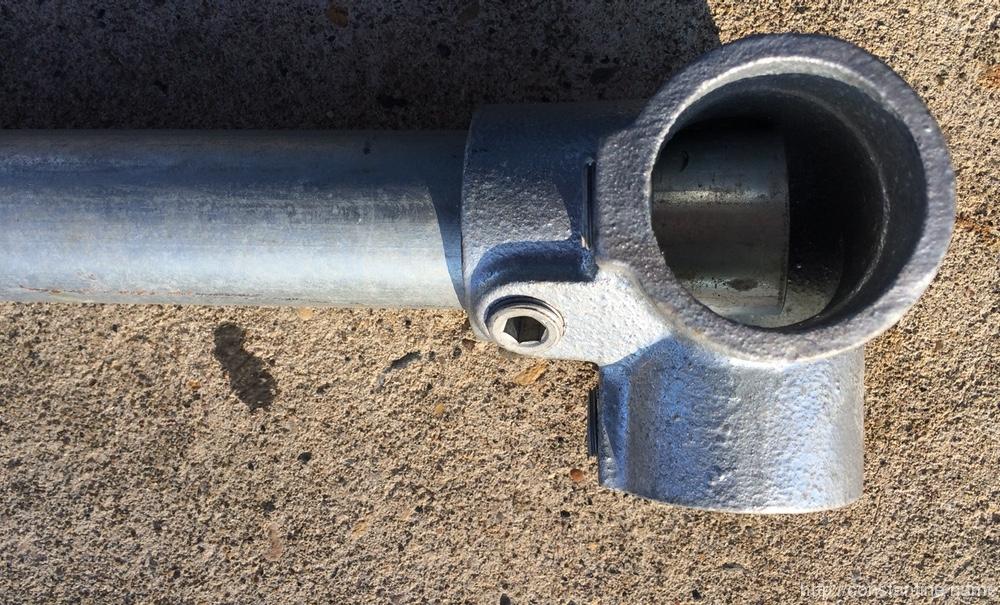
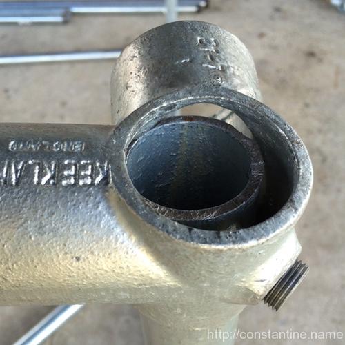
Above: Lands are the extreme nearest and farthest sides of this clamp. Set screw is pressing from the right, so the pipe will touch the lands on the left. Also, the pipe will have to go all the way through (protruding slightly) on both sides of this clamp.
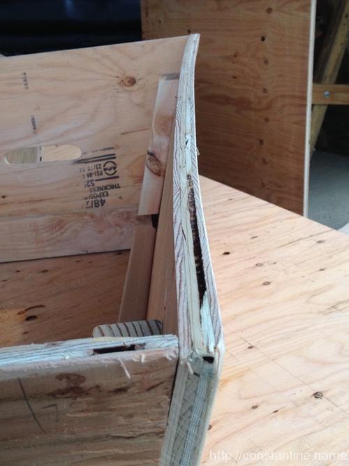
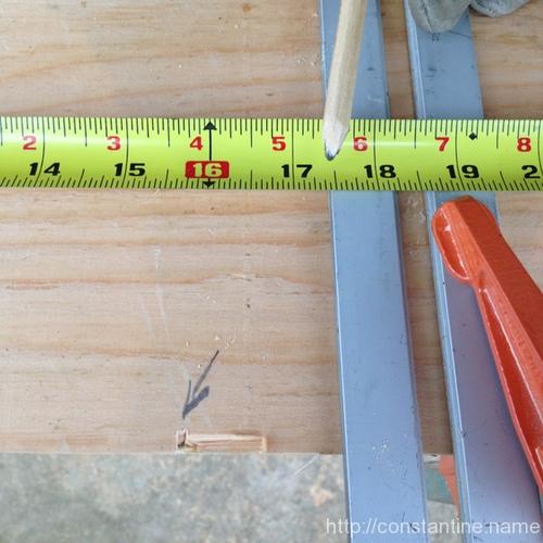
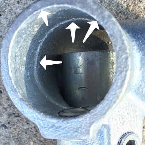
In the next photo is a similar clamp where the pipe is not through (upwards towards the viewer) far enough to reach the land at the top opening of the clamp. This pipe could wiggle loose. As it is now, tightening the screw will drive the pipe into the clamp body. It looks like the end of the pipe will touch the clamp body where the body is rounding from one side-out to the other side-out. There, the body is curved (convex) enabling the pipe end to wiggle; compared to the land (concave) at the pipe opening face which would cradle the pipe.
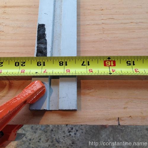
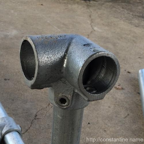
Next is just another shot of a clamp, its lands and the set screw on the bottom. Remember, you have to understand, and insert the pipes correctly when you cannot actually see what’s going on.
Once you get the feel for this, you’ll recognize when you have it right. The pipe will be loose in the clamp initially. As you tighten the screw, the pipe will move to the opposing side of the clamp. Ideally, if you have it all lined up right, it reaches the lands at the same time (or things are loose enough that the clamp pivots easily to bring the second land into contact). When you do it wrong, you get one land, and the pipe hits the clamp body or the mis-aligned clamp just torques against the screw-and-one-land. That’s a recipe for wiggling-loose.
At this point, you should see why you don’t simply stuff the pipes into the clamps as far as possible and then tighten the screws. It’s all about having sufficient insertion depth to reach the lands.
Next is a photo of “this looks good”. It’s a good sign when all the space is on the side with the screw, and you can see the pipe is flush up against the other side (i.e., against the land). What you cannot see, but have to feel, is whether the pipe “registered” (i.e. “found it’s correct location”) when the end of the pipe in the clamp was driven to its land.
One last item: Now that you know where the six lands in this clamp have to be, you understand how you could choose how far extra to insert the pipes. Any one of these three could be inserted (roughly) an extra half-pipe-width to occupy the central hollow of the body. Or, all three could be democratically not inserted beyond the interior land.
Mastery
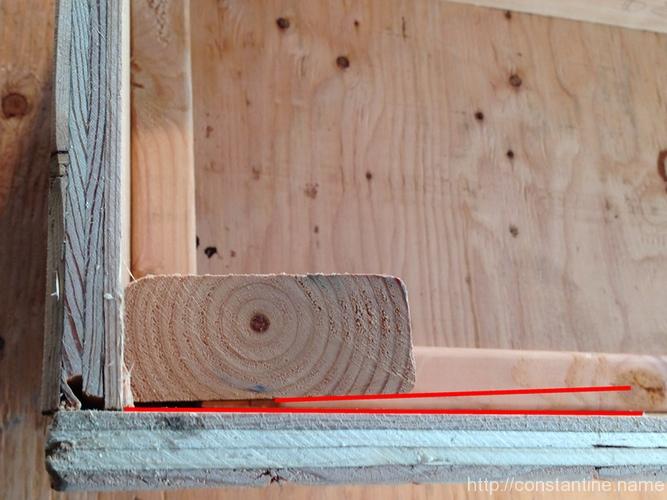
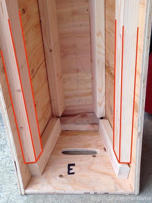
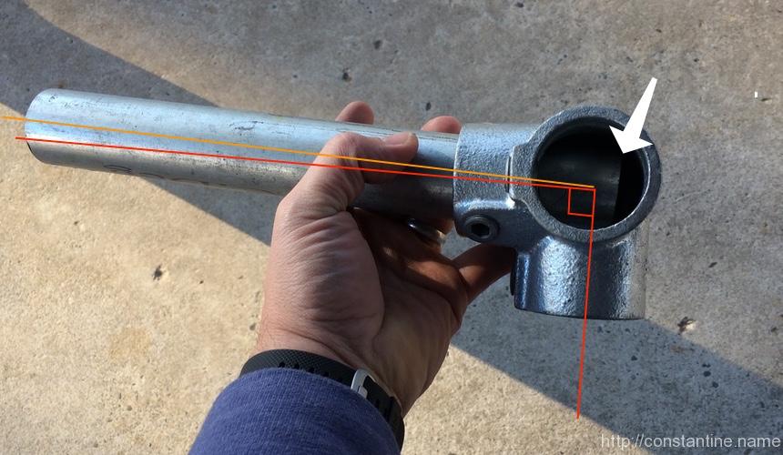
In the next photo, you should now have an “a-HAH!” moment about why the threaded pipe ends are a bad thing. (Which, we’re only dealing with because this is “getting started with scaf on the cheap.”)
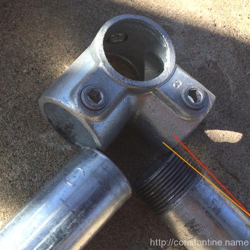
I’ve drawn the red line parallel to the pipe’s side and offset a little so you can still see the pipe. I’ve drawn the orange line parallel to the threads (and offset a bit so you can see the threads.) Now, the pipe on the left could touch the inward land at the end of the pipe (because no taper). But the pipe on the right has it’s diameter reduced slightly by the thread cutting producing a tapered end. So if you put the threaded pipe in so the threads just reached the inward land then the pipe (or the clamp) will be pulled slightly on an angle as the pipe end has to be driven just a smidge farther to reach the land.
So it turns out that if you know this little detail you can do things like orient all the 3-foot pieces (which all have a thread on one end) the same way, and insert them all father into the clamp body so the unthreaded pipe body reaches the inward land. To do that you have to not insert some other pipe into the clamp and occupy the middle space. You’ll see an example of this in the first build. And this little trick about how to insert threaded ends just a little farther only makes sense once you understand lands and how the clamps work.
Look away, insanity ahead: So know you understand that pipe threads are bad for our scaf build. What to do? Easy, buy all your pipe by the bundle via freight without the threads. (Wee! …thousands of dollars.) Or, on the longer pieces where an inch doesn’t matter (you know, those 7-foot pipes Depot cut for you from 10-foot sticks) just cut the threads off the end of each pipe with a hacksaw. Or cut all the threads off all the pipe and deal with the fact that your scaf all has an inch missing here and there. Or, go full-on insanity mode, buy a lot of extra pipe from Depot, cut all your scaf pipe in perfect integral-foot sizes withOUT the threads, and recycle all the odd-sizes you end up with. (Bring the pipe home uncut, start with a 10-footer, cut off an inch, cut off a 7-footer, cut off a 2-footer, throw away the other few inches. etc. You can make a 9’10” stick, one-8-and-one-1, 7-and-2, 6-and-3, 5-and-4 if you’re willing to make a ZILLION hacksaw cuts.)
Whizardy
In the beginning, remembering which way to orient the 45° single outlet tees can be tricky (because they go onto different pipes at different times as you’re assembling). But beyond that, angle braces are actually pretty hard to assemble well.
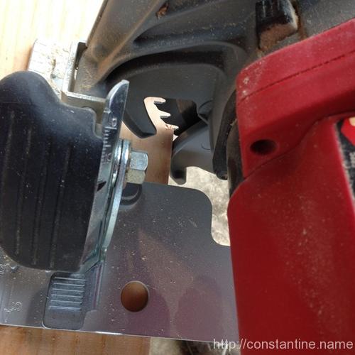
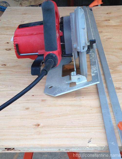
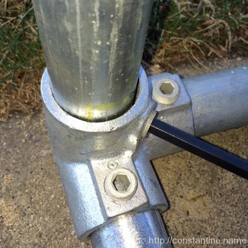
Exercise: Let’s look at this photo and make some wild guesses about of what might be going on…
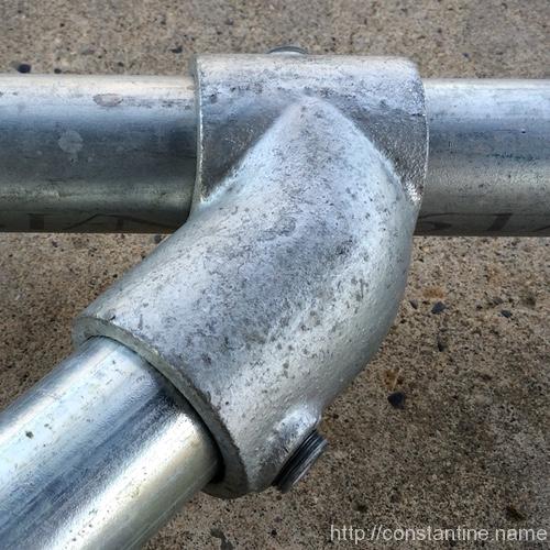
- The set screw towards the bottom of the photo is snug. Gap is on the screw side. But probably not fully tightened because the screw seems to be a little proud (sticking out too far.) Opposing side of pipe has no gap, good.
- No idea if the pipe is in so far that it’s hitting the other pipe, instead of resting in the inward land. Hmmm, would have to feel that as it was put together. WAIT… why is that screw so proud? Maybe the end of the pipe is hitting the upper pipe, that would twist the pipe clockwise, I can see the outside land is tight. Oh, the pipe is in too far. Or the pipe is being held by hand and that screw isn’t tight at all. Gah! …this is hopeless.
- The upper screw seems to be not at all tight because the clamp is resting on the pipe (down toward the concrete.
- IF the lower screw is tight, and IF the lower pipe is correctly landed, then the orientation of the angle brace is off; it needs to have it’s left end (out of the photo) moved clockwise. What? Why? …look at the alignment of the clamp at the very top edge and that side of the pipe. The whole clamp needs to rotate clockwise.
The best way to assemble these angles is to slide the clamps along their side pipes, and insert the brace pipe into both clamps at once. Then, get one end of the brace pipe on both lands (without inserting it so far that it hits the other side pipe in the tee), and tighten the screw moderately. Next, do the other end of the brace. Hopefully, you can still wiggle and shift the clamps on the side pipes, because you need to orient the brace so that both of the clamps will land correctly when you tighten the screws to lock them onto the side pipes. You will only be able to make all four lands on the side pipes touch if the corner is close to a 90° angle. Sometimes you land/clamp the ends onto the brace piece, only to discover that you can then not get the clamps to land perfectly on the side bars. But, if you get all eight lands to touch, you will have an insanely strong corner. Unfortunately, building good angle braces is something you just have to learn by doing.
Bam! You’re now a clampion. (What’s with the puns? I know, right!) But, as I sad at the very beginning, I wish someone had put all this together in one place when I started. Having read to this point, you have now just saved yourself about a year of “learning the hard way” about how to build with scaf.
ɕ